32 circuits
From an LED and its resistor to a microcontroller. Each one has a breadboard you can touch.
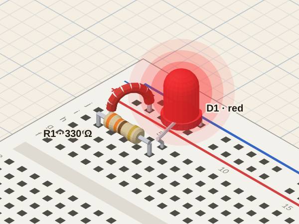
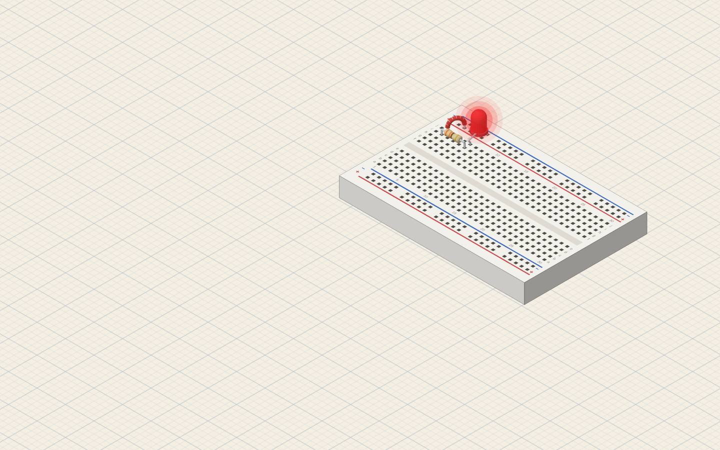
LED with a series resistorThe resistor sets the LED current: I = (V − Vf) / R
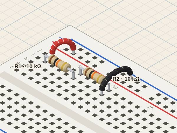
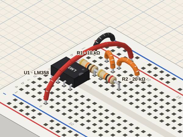
Voltage dividerVout = Vin · R2 / (R1 + R2), measured where the two resistors meet
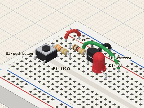
NPN transistor switchA small base current switches a larger collector current (press S1)
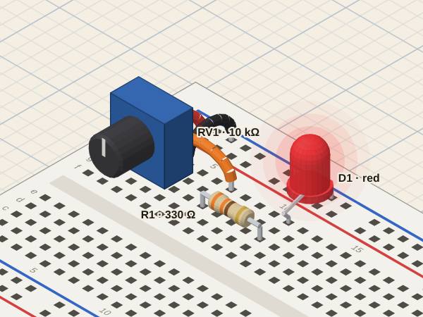
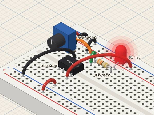
Potentiometer dimming an LEDThe wiper is an adjustable divider: its voltage goes from 0 to the supply
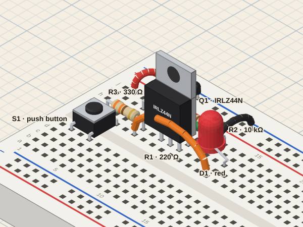
MOSFET switchThe gate takes voltage, not current; the pull-down R2 discharges it when S1 is released
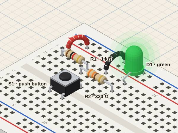
Button with a pull-up resistorReleased, R1 pulls the output up (LED on); pressed, S1 takes it to ground (LED off)
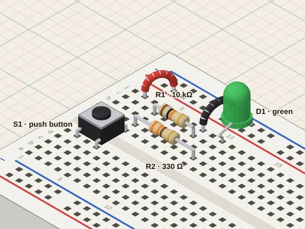
Button with a pull-down resistorReleased, R1 holds the output at ground (LED off); pressed, S1 takes it to the supply (LED on)
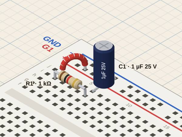
RC circuit with a square waveC1 charges and discharges with τ = R·C; compare it with the period of G1
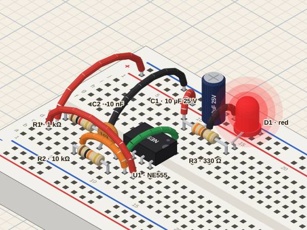
555 astable blinking an LEDC1 charges through R1 + R2 and discharges through R2: f ≈ 1.44 / ((R1 + 2·R2) · C1)
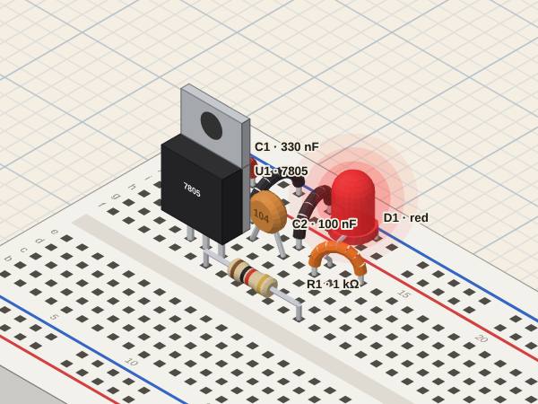
7805 regulator with a pilot LEDA fixed output from a higher input; the difference is lost as heat in U1
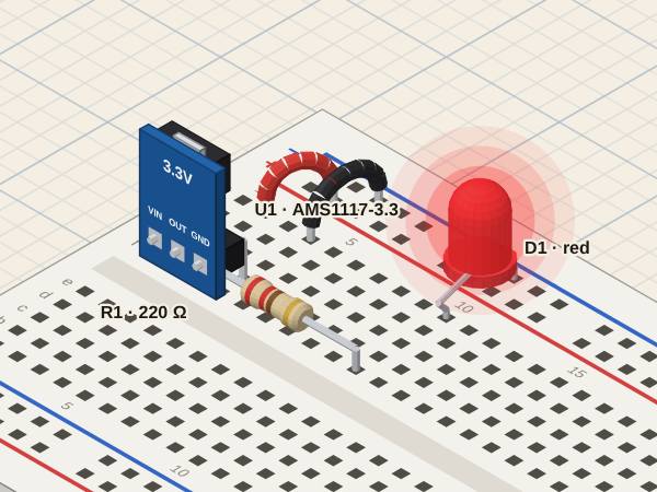
AMS1117 module with an LEDA low-dropout regulator: 3.3 V out from 5 V in
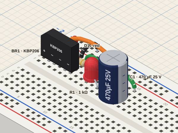
Bridge rectifier with a filter capacitorBoth half-waves come out positive; C1 fills the gaps between peaks (ripple)
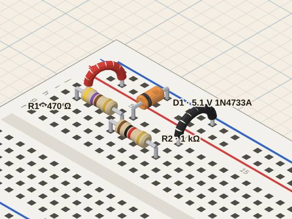
Zener regulatorReversed, the Zener holds its voltage; R1 takes the rest of the supply
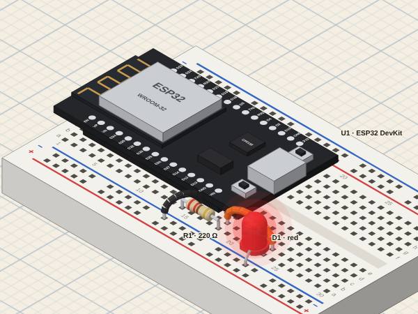
ESP32 blinking an LEDA GPIO pin as an output: digitalWrite(13, HIGH) lights D1, delay() sets the rhythm
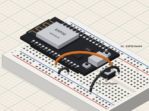
ESP32 reading a buttonA GPIO pin as an input with the internal pull-up: digitalRead(27) reads LOW while S1 is pressed
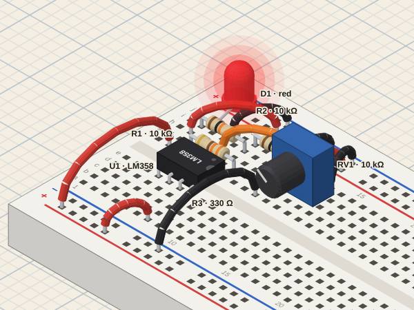
Op-amp comparatorWithout feedback the output saturates: high when V+ > V−, low when V+ < V−
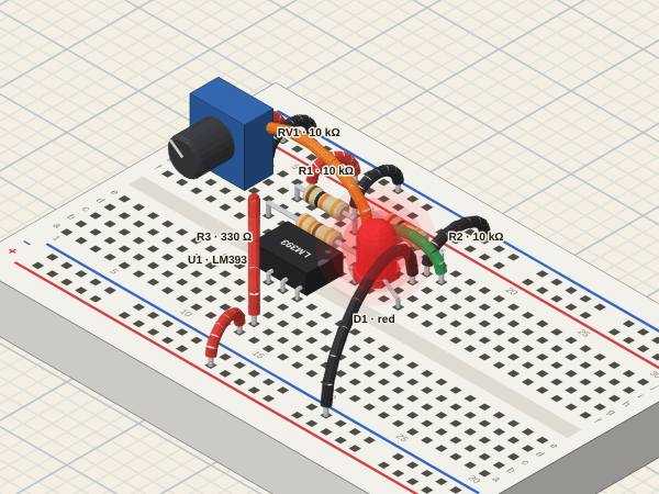
LM393 comparator (open collector)The output only pulls down: the LED, fed from the supply, lights while V− > V+
Op-amp voltage follower (buffer)With the output on V−, the output copies V+: the potentiometer gives a voltage, the op-amp gives the current
Non-inverting amplifierGain = 1 + R2/R1: the output is the input times 3, in phase
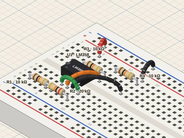
Inverting amplifierGain = −R2/R1 around the reference on V+: the output is twice the input, upside down
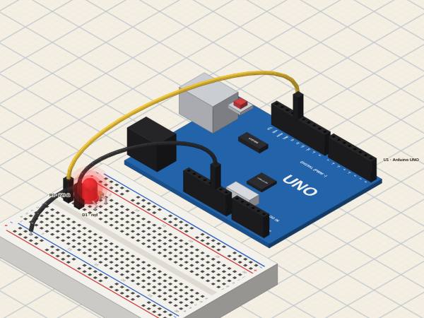
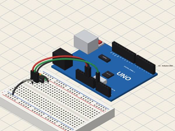
Arduino UNO blinking an LEDA pin as an output at 5 V: digitalWrite(13, HIGH) lights D1, delay() sets the rhythm
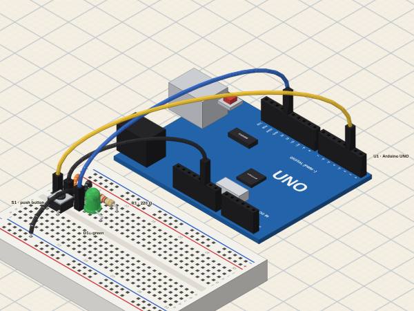
Arduino UNO: a button lights an LEDA pin as an input with the internal pull-up: it reads LOW while S1 is pressed, and the program decides the LED
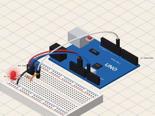
Arduino UNO: a potentiometer dims an LED (ADC and PWM)analogRead turns a voltage into 0…1023; analogWrite turns 0…255 into the share of time the pin is high
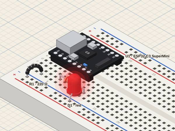
ESP32-C3 SuperMini blinking an LEDA GPIO as an output at 3.3 V: digitalWrite(3, HIGH) lights D1
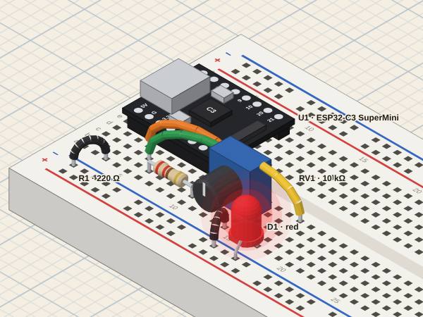
ESP32-C3: a potentiometer dims an LED (ADC and PWM)analogRead turns a voltage into 0…4095 (12 bits, up to about 2.5 V); analogWrite sets the share of time the pin is high
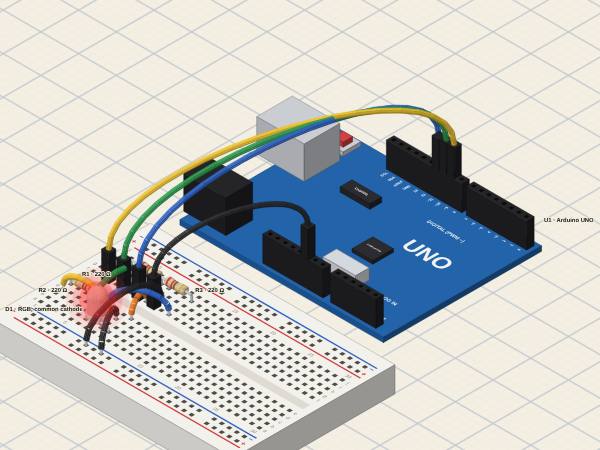
Arduino UNO: an RGB LED mixes colours (PWM)Three LEDs in one dome, each with its own resistor: their brightness, set by PWM, adds up to the colour the eye sees
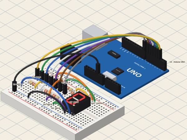
Arduino UNO: a 7-segment display counts 0 to 9Seven LEDs to one common pin, each with its own resistor: a digit is the set of segments the program lights
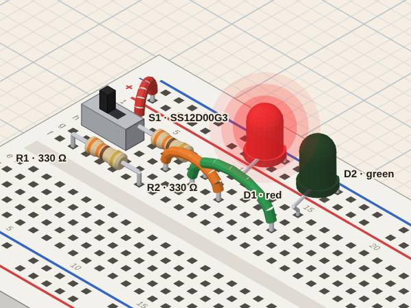
Slide switch picks an LEDA changeover (SPDT): its middle pin is joined to one end or the other, so one switch sends the current down one of two paths
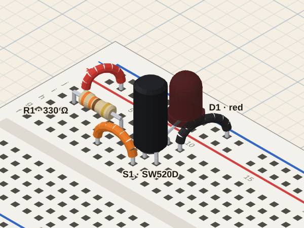
Tilt switch alarmUpright, the closed switch takes the resistor's current past the LED; tilted, it opens and the LED gets it
Arduino UNO: LM35 thermometerThe LM35 turns temperature into 10 mV per °C; the ADC turns that voltage into a number, and the program back into degrees
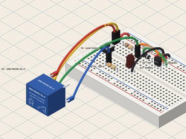
Relay with an NPN and a flyback diodeA small base current lets the coil's 71 mA flow; the coil pulls the contact over and the LED lights. Released, the diode takes the coil's current (without it, its voltage would jump far past the supply)
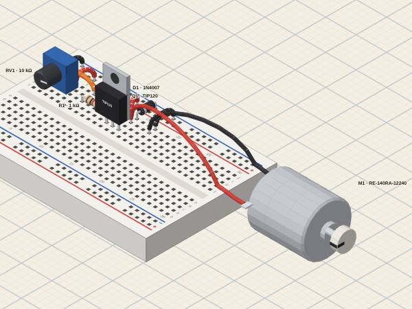
DC motor speed with a transistorStarted, the motor draws nearly its stall current and speeds up with a time constant of its inertia; turning, its back-EMF rises with the speed until it nearly balances the supply, and the current falls
No circuits on this topic yet. Try «All».